DLW Associates
AM Broadcast Band (BCB) Reject Brick-Wall High Pass Filter

FL1718 - AM Broadcast Band Reject Brick-Wall
High Pass Filter -
This high pass filter is intended to be placed between
a HF transceiver output and an amplifier or antenna
tuner. It is optimized for a 50 ohm input and output
impedance. The filter is a 9th order elliptic design that
has a very sharp slope occurring between 1.8MHz
and 1.7 MHz. The FL1718 effectively attenuates all
AM broadcast band signals by over 40 dB. The filter
is packaged in a cast aluminum (o-ring seal) case
with SO239 flanged teflon dielectric coaxial fittings.
The components consist of high-Q high voltage NPO
ceramic or mica capacitors and high Q toroidal coils
mounted on a two sided printed circuit board. The
PCB and coils are conformal coated. All mounting
hardware is stainless.
We offer modifications to this basic filter model that can enhance performance for difficult user applications. These modifications are
provided at no additional cost to the user as long as housing and PCB remain common to the design. Changes usually consist of
moving a stop band or pass band endpoint and placing a filter null over an interfering frequency. Call or email for a free consultation
on your particular interference problem.
Filter Specifications
Maximum power rating: 200W CW or SSB
Pass band loss: < 0.85dB (1.8 - 54 MHz )
Stop band loss: > 40dB (1.7 MHz and below)
Return loss: > 20dB (1.8 - 54 MHz)
Nominal Size: 5"L x 3.2"W x 2.3"H
Shipping Weight: 2 lbs
Filter Performance
The model and spectrum plots of the filter showing the signal frequency Vs the amplitude response of the filter when connected to a
sweep generator and an actual antenna are presented below.

Filter Model
This is a graph of the insertion and return loss calculated
by the filter design model generated by the filter design
tool.
The design is a 9th order elliptic filter that has the ability to
provide a very sharp transition from pass band to loss
band.
Each null in the graph represents a high Q series
resonant response from each of the four coil/capacitor
sets.
These nulls can also be seen in the filter swept response
depicted below.
Filter Insertion Loss (Shown on HP3577A Vector Network Analyzer)

Broadcast band Spectrum - With No Filter Installed (Shown on SDR-14 Spectrum Analyzer)
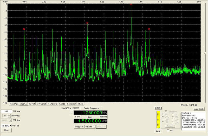
The station at 1120KHz is running 50,000 Watts. The close-in 1460KHz station is only running 5000 Watts but uses a highly
directional antenna to increase it's effective power toward my location (within 5 miles) and is showing a reading near 0 dBm.
Broadcast band Spectrum - With Filter Installed (Shown on SDR-14 Spectrum Analyzer)

With the filter installed the station at 1460KHz is down 47 dB and the one at 1120KHz is down 50 dB.

.
About Us
I retired in 2001 after working as
an electronics design engineer for
over 40 years at eight different
companies. We then turned to
consulting.
However, I thought that with the
technology available today it might
be feasible to design, develop and
market one or more of my own
products. The filter presented on
this page is my first product.
I have been an amateur radio
operator (present call sign AB0SA)
since 1952 and I designed and built
my first single sideband exciter in
1956.
In my present location I am less
than five miles from a highly
directional 5,000 Watt AM radio
station. My transceiver front end
was being blocked by the strong,
near 0 dBm signal at 1460KHz on all
the low HF bands. My receiver S
meter only displays to 60dB over S9
which is -13dBm.
I could not find a commercial filter
for sale that had a significant loss
over the entire AM band, especially
at the upper end (1700KHz) without
effecting the use of the 160 meter
band starting at 1800KHz.
The filter presented here was
developed in 2006 and meets my
criteria for loss over the entire AM
Broadcast Band while allowing full
use from 1800KHz through 54MHz.
Ordering:
The base price of the filter is
$195.00USD. Postage and handling
is a flat rate of $10 within USA.
Filters are shipped via USPS
Priority Mail Service.
International customers should
email us for a shipping/handling
quotation tailored for their specific
location..
Sales Tax: For sales to customers
with Missouri addresses we will add
7.45%.
Payment: Within USA; personal or
company check, money order or
PayPal.
For customers outside USA we
only accept PayPal.

Options: N connectors can be
substituted for SO-239 connectors
at no additional charge.

Contact
| ©2006-2015 DLW Associates

stocks standard FL1718 filters
DLW Associates
AM Broadcast Band (BCB) Reject Brick-Wall High Pass Filter
FL1718 - AM Broadcast Band Reject Brick-Wall
High Pass Filter -
This high pass filter is intended to be placed between
a HF transceiver output and an amplifier or antenna
tuner. It is optimized for a 50 ohm input and output
impedance. The filter is a 9th order elliptic design that
has a very sharp slope occurring between 1.8MHz
and 1.7 MHz. The FL1718 effectively attenuates all
AM broadcast band signals by over 40 dB. The filter
is packaged in a cast aluminum (o-ring seal) case
with SO239 flanged teflon dielectric coaxial fittings.
The components consist of high-Q high voltage NPO
ceramic or mica capacitors and high Q toroidal coils
mounted on a two sided printed circuit board. The
PCB and coils are conformal coated. All mounting
hardware is stainless.
We offer modifications to this basic filter model that can enhance performance for difficult user applications. These modifications are
provided at no additional cost to the user as long as housing and PCB remain common to the design. Changes usually consist of
moving a stop band or pass band endpoint and placing a filter null over an interfering frequency. Call or email for a free consultation
on your particular interference problem.
Filter Specifications
Maximum power rating: 200W CW or SSB
Pass band loss: < 0.85dB (1.8 - 54 MHz )
Stop band loss: > 40dB (1.7 MHz and below)
Return loss: > 20dB (1.8 - 54 MHz)
Nominal Size: 5"L x 3.2"W x 2.3"H
Shipping Weight: 2 lbs
Filter Performance
The model and spectrum plots of the filter showing the signal frequency Vs the amplitude response of the filter when connected to a
sweep generator and an actual antenna are presented below.
Filter Model
This is a graph of the insertion and return loss calculated
by the filter design model generated by the filter design
tool.
The design is a 9th order elliptic filter that has the ability to
provide a very sharp transition from pass band to loss
band.
Each null in the graph represents a high Q series
resonant response from each of the four coil/capacitor
sets.
These nulls can also be seen in the filter swept response
depicted below.
Filter Insertion Loss (Shown on HP3577A Vector Network Analyzer)
Broadcast band Spectrum - With No Filter Installed (Shown on SDR-14 Spectrum Analyzer)
The station at 1120KHz is running 50,000 Watts. The close-in 1460KHz station is only running 5000 Watts but uses a highly
directional antenna to increase it's effective power toward my location (within 5 miles) and is showing a reading near 0 dBm.
Broadcast band Spectrum - With Filter Installed (Shown on SDR-14 Spectrum Analyzer)
With the filter installed the station at 1460KHz is down 47 dB and the one at 1120KHz is down 50 dB.
.
About Us
I retired in 2001 after working as
an electronics design engineer for
over 40 years at eight different
companies. We then turned to
consulting.
However, I thought that with the
technology available today it might
be feasible to design, develop and
market one or more of my own
products. The filter presented on
this page is my first product.
I have been an amateur radio
operator (present call sign AB0SA)
since 1952 and I designed and built
my first single sideband exciter in
1956.
In my present location I am less
than five miles from a highly
directional 5,000 Watt AM radio
station. My transceiver front end
was being blocked by the strong,
near 0 dBm signal at 1460KHz on all
the low HF bands. My receiver S
meter only displays to 60dB over S9
which is -13dBm.
I could not find a commercial filter
for sale that had a significant loss
over the entire AM band, especially
at the upper end (1700KHz) without
effecting the use of the 160 meter
band starting at 1800KHz.
The filter presented here was
developed in 2006 and meets my
criteria for loss over the entire AM
Broadcast Band while allowing full
use from 1800KHz through 54MHz.
Ordering:
The base price of the filter is
$195.00USD. Postage and handling
is a flat rate of $10 within USA.
Filters are shipped via USPS
Priority Mail Service.
International customers should
email us for a shipping/handling
quotation tailored for their specific
location..
Sales Tax: For sales to customers
with Missouri addresses we will add
7.45%.
Payment: Within USA; personal or
company check, money order or
PayPal.
For customers outside USA we
only accept PayPal.
Options: N connectors can be
substituted for SO-239 connectors
at no additional charge.
Contact
| ©2006-2015 DLW Associates